Motorcycle Alarm
 Schematic Schematic  and board layout and board layout |
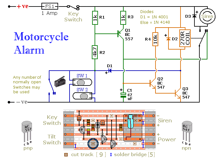
Parts List and Board Layout Showing Part Locations
|
Gadget's Finished (and working) circuit
|
Click Thumbnails For Larger Image
Why pay $75 and up for a motorcycle alarm system when you can build your own for about $10 (not including siren and key switch if you choose to use them)?
Ron Moloney has created this simple circuit using common off the shelf parts that most anyone with a soldering iron can put together.
Once the board is done it's up to you to decide whether you want to protect bags with switches, the steering or????
Read the descriptions carefully and you'll find there is no need for a remote control.
This circuit can be set up to arm automatically when you turn off your ignition (or you can use a hidden switch).
The alarm timing is adjustable with a bit of experimentation. Ron has set it up so the siren (or your bikes horn) will sound for about two minutes.
If 30 seconds is enough then modify the value of C-1.
The following descriptions of the circuit and its workings were written by Ron.
I have sectioned them off with the first part suitable for those of us who don't know and don't care why one part interacts with another.
The second part is for those who want to know 'why' it works and 'why' Ron decided to use certain parts.
In the event you don't have a decent electronics parts store in your area (don't even bother with Radio Shack anymore) you can purchase all of the
If you want to add an LED armed/disarmed light someplace on the bike just purchase a 12 volt LED and connect the positive (+) side
to the switched side of your on/off switch, the negative (-) side of the LED goes to ground. That way you can tell from a distance whether
the system is armed or not as can potential thieves.
|
Pricing and Part Numbers from Mouser Electronics
660-CF1/4L102J CF1/4L102J.......1K OHM 5% BULK....................2..........$ 0.05.. $ 0.10
660-CF1/4L103J CF1/4L103J.......10K OHM 5% BULK..................1..........$ 0.05.. $ 0.05
660-CF1/4L472J CF1/4L472J.......4.7K OHM 5% BULK................ 1..........$ 0.05.. $ 0.05
512-BC547....................................NPN TRANSISTOR................... 2..........$ 0.21.. $ 0.42
512-BC557......................... .........PNP TRANSISTOR.................... 1..........$ 0.21.. $ 0.21
512-1N4001..................................1N4001 DIODE........................... 1..........$ 0.05.. $ 0.05
512-1N4148.................................1N4148 DIODE............................ 2..........$ 0.04.. $ 0.08
107-1006....................................NO MERCURY TILT SWITCH..... 2..........$ 0.73.. $ 1.46
140-XAL16V47...........................16V 47uF 20%............................... 1..........$ 0.25.. $ 0.25
431-1712....................................RELAY 12VDC SPDT DIP..............1..........$ 2.05.. $ 2.05
53-D2F-FL....................HINGE LEVER SWITCH GP PCB.............. 2..........$ 1.06.. $ 2.12
Total: $6.84
This does not include the siren or keylock (arm/disarm switch)
|
And now we turn it over to Ronald:
Part 1 The Simple Stuff:
The circuit board and switches must be protected from the elements. Dampness or condensation will cause malfunction. Without its terminal blocks, the board is small. Ideally, you should try to find a siren with enough spare space inside to accommodate it. Fit a 1-amp in-line fuse close to the power source. This protects the wiring. Instead of using a key-switch you can use a hidden switch; or you could use the normally closed contacts of a small relay. Wire the relay coil so that it is energized while the ignition is on. Then every time you turn the ignition off, the alarm will set itself.
When it's not sounding, the circuit uses virtually no current. This should make it useful in other circumstances. For example, powered by dry batteries and with the relay and siren voltages to suit, it could be fitted inside a computer or anything else that's in danger of being picked up and carried away. The low standby current and automatic reset means that for this sort of application an external on/off switch may not be necessary.
Fit the mercury switches so that they close when the steering is moved or when the bike is lifted off its side-stand or pushed forward off its center-stand. Use micro-switches to protect removable panels and the lids of panniers (saddlebags) etc. While at least one switch remains closed, the siren will sound. About two minutes after the switches have been opened again, the alarm will reset. How long it takes to switch off depends on the characteristics of the actual components used. But, up to a point, you can adjust the time to suit your requirements by changing the value of C1.
Part 2, All The Nuts And Bolts
Circuit Description:
I designed the alarm primarily for a motorcycle but I also had in mind the other uses to which it might be put. I had had a number of requests for a circuit that could be built into a computer and would sound the alarm if the computer were picked up by a thief. Such an alarm would have to be battery powered so the standby current would have to be small.
I didn't do any calculations as such. I started with two general purpose npn transistors that can handle a maximum current of 100mA. Then I choose a relay that required a current of about 40mA so the transistors would not be overloaded. The pnp transistor was chosen because it was pnp. There is nothing special about it. The value of the capacitor was chosen by trial and error to give a reset time of about 2 minutes.
I choose the resistor values to be on the low side because I didn't want the circuit to be too sensitive to moisture in the air. So all the transistors are turned hard off and no current will leak through them.
The switches are fitted so they close if the motorcycle is moved. Exactly how and where the switches are fitted will depend on the type of motorcycle and the type of switches used. So I cannot say how the alarm should be fitted other than that the fuse should be as close to the power source as possible; and the switches, circuit, and siren should be made as inaccessible as possible.
The alarm was designed to have a very low standby current so it can be powered by either the motorcycle battery or by its own dry battery. For this reason, normally-open switches were chosen as the triggers since in standby mode they pass no current. When one of the switches is closed, the negative side of the relay coil is connected to ground through D1. This energizes the relay and sounds the siren.
It also provides forward bias for the base of Q1. This allows Q1 to conduct and R3 charges the capacitor. C1 is part of the latching circuit that keeps the relay energized after the trigger has been re-opened. I wanted the relay to latch quickly so even a brief closing of the trigger would activate the alarm. That is why R3 is a 1k resistor. It charges C1 very quickly.
I also used a 1k resistor for R1. This is intended to hold Q1 firmly off so there can be no tendency for Q1 to leak. If R1 were a very high value condensation or other moisture might tend to permit Q1 to conduct.
When charged, the voltage across C1 is about 1.6 to 1.7 volts. This limit is set by the base-emitter junctions of Q2 and Q3. If R2 were not present the base-collector junction of Q1 would hold C1 at 0.6 to 0.7 and prevent it from reaching a high enough potential to switch Q2 and Q3 on. The value of R2 is not very critical. I choose 4.7K, but any value that turns Q1 on and holds its base above about 2 volts will do.
The alarm sounds when current through D1 energizes the relay. But after the trigger is re-opened, it's Q3 that keeps the relay energized. You can use any 12-volt relay but the coil should have a resistance of about 270 ohms or higher. This gives a maximum current of about 45 mA, and Q3 will easily be able to handle it.
As well as charging C1, current through Q1 switches Q2 on. Then current through R4 and Q2 switches Q3 on. R4 is there to limit the current through the base of Q3. When the trigger is re-opened and Q1 switches off, Q2 is held on by the charge stored in C1. This in turn keeps Q3 switched on so the relay remains energized and the siren continues to sound.
Because they are connected as a sort of Darlington pair, the input impedance of Q2 and Q3 is very high and C1 discharges slowly. The time it takes depends on the characteristics of the actual components used, particularly the hfe of the transistors. As C1 discharges, the current through Q2 falls as the base current through Q3 falls and its collector-emitter voltage rises. This reduces the voltage across the relay coil and it eventually drops out.
However, although they can no longer hold the relay in, Q2 and Q3 would continue to conduct to some degree and this would waste energy and lead to an increased standby current. To prevent this, the base of Q2 is connected to the normally closed contact of the relay. When the relay drops out, the base of Q2 is taken to ground. This completes the discharge of C1 and turns Q2 and Q3 firmly off. In this condition, the standby current is virtually zero.
D1 is there to prevent accidental damage to Q3 during the building, testing, and installation of the alarm. If, while Q3 is switched on, the wire going to the switches were to come in contact with the positive rail, the transistor would be destroyed. Although a 1N4148 might do for D1, I felt that for the sake of reliability the more robust 1-amp, 1N4001 would be better.
The volume of the siren is related to the current it draws. The more current - the louder the noise. A typical siren will take about 300mA.
If the alarm switches are fitted properly, the circuit should reset about 2 minutes after the bike has been returned to its center-stand or kick-stand.
If it's not returned to one of its stands (e.g. it's left lying on the ground or leaning against a wall) and one of the switches remains closed, the siren will continue to sound indefinitely.
With a 12 Amp/Hour battery the siren will sound for about 40 Hours before the battery becomes completely flat. So even after 8 to 10 hours of sounding there should still be enough power left to run the machine.
Relay coils and some sounders can produce high reverse voltage spikes that will destroy sensitive electronic components. D2 and D3 are there to short-circuit the spikes before they can do any damage. Although there is nothing in the alarm circuit itself that could be damaged, I have no idea what other electronic equipment might be connected to the same supply. So I included the two diodes as a precaution.
Comments (0)
You don't have permission to comment on this page.